
Introduction to Vgaterm

Over the past two years or so my friend Seth and I have been building a hardware terminal. Or at least, we started building something and it eventually became a terminal!
This pandemic project was a way for us to connect with each other and learn new technical skills while building something that would allow us to physically connect computers together.
A hardware terminal is an old-school way of connecting a user to a mainframe - or a multi-user computer. A terminal has a keyboard and monitor and a “serial” connection to a computer that many other people could be using at the same time with their own terminals. It’s the physical device that you might have had on your desk in 1975, and that now exists as software emulating that hardware. That’s why your favorite program where you might type ls to list files in a directory is called a “terminal”: it’s short for “terminal emulator”! To learn about terminals and how they’ve shaped computing history, I’d absolutely recommend this blog post.
Terminals are largely not in use any more because computers are cheap and everywhere and can just connect to each other over the internet. You may remember using a hardware terminal (up to the late 90s, perhaps) at your local or school library to browse the available books in the catalogue. I remember my elementary school likely used VT terminals in their library!
This is the start in a series of posts all about the planning, building, and philosophy of Seth and I making a hardware terminal in 2024.
This post will specifically be about the basic workings, pictures, and how we were inspired to make something like this.
The Start
My technical background is mostly java, python, and the web. So a part of me has always wanted to learn more systems and lower-level programming. When Rust came around I was excited to learn a new systems language with an interesting type system. At some point many years back during a conversation over pizza, Seth and I decided to make a Github org for playing with Rust and learning low level programming. We called it Rustbox, as the original conceit was to make an operating system together in rust.
At some point I learned about RISC-V, an open source instruction set for CPUs, and decided I wanted to try programming rust for RISC-V, and Seth and I bought a few HiFive boards. Inspired by Ben Eater’s youtube video “Making the Worlds Worst Video Card” using a 6502 processor, I decided to make the hifive board into a “video card”. After a year I had a set of breadboards and a RISC-V CPU displaying images and text using my own font. It output a VGA signal in the 640x480 mode made up of 160x96 actual pixels, each with 64 possible colors (due to memory constraints):


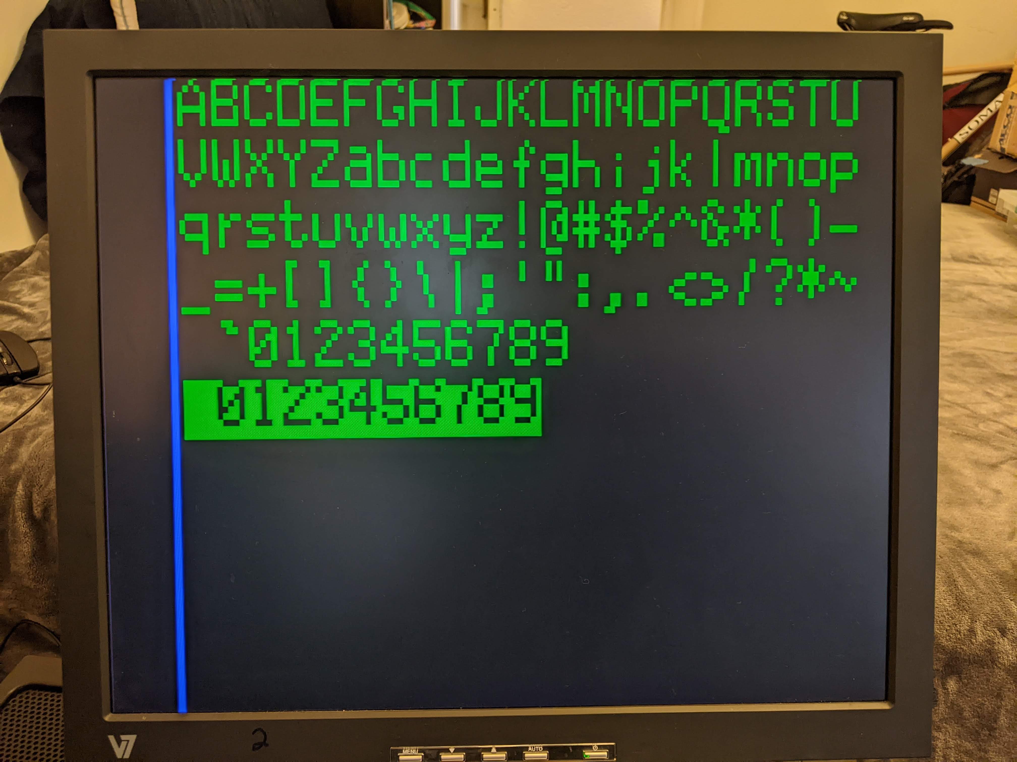
Code for this project can be found here
Vgaterm
The hifive board video card was neat and I learned a lot but I wanted it to be useful somehow. In the hifive code I had also made some command line bare metal programs as well as having the characters update from keyboard input. I was also always a little sad that I needed a large computer to be attached to my small computer to run and interact with it (e.g. through screen or other terminal program). Thus I realized I wanted to make a physical terminal, and upgrade the VGA capabilities. So Seth and I embarked on making Vgaterm: a hardware terminal that would would output 640x400 pixels at 256 colors, connect to serial IO, receive keyboard input, and display text updates to the screen. The goal was to be able to log in to a standard linux machine with the hardware and interact on the command line - and hopefully use any standard terminal programs like Vim, etc.
The final device uses an esp32c3 microcontroller and custom designed circuit boards hand soldered together.


Technical Overview
Since the new device aspirationally would output VGA at the full 640x480 60Hz standard we needed a microcontroller that would:
- have at least 300 KB of fast memory for the video buffer (1 byte per pixel, giving us 256 colors)
- have some memory for coordinating IO and other tasks
- fast enough to output pixels for the VGA pixel clock at 25.175 MHz: 39.7 ns per byte
Additionally, part of the philosophy of the project was to celebrate and engage in open hardware and software. So keeping a RISC-V core felt crucial to our goals.
Finding the esp32c3 by Espressif seemed to fit the bill by the numbers:
- 400 KB SRAM
- 4 MB Flash Memory
- 160 MHz CPU
- 15 GPIO pins
However, it turned out that bit-banging 8 GPIO lines as fast as possible on the esp32c3 was not quite fast enough because of limitations on the device. Additionally there wasn’t an obvious way to match the VGA clock domain from the CPU. To get the pixel timing right we would need to time out intervals of 39 ns - the period of the VGA pixel clock. At 160 MHz CPU clock speed that’s only 6 cycles per pixel period. Additionally we’d need the timing for the other VGA signals (VSYNC and HSYNC) to be quite precise and it just didn’t seem feasible to generate those timings within the CPU.
To solve the clock domain issue we decided to use a FIFO memory (first in first out, like a queue) chip. So the CPU writes bytes into the FIFO, and the VGA hardware reads from the FIFO at a different rate. As long as the CPU can write bytes within a certain tolerance, the CPU and the VGA display hardware needs to only be loosely coupled.
To solve the speed issue we utilized the esp32c3 quad SPI module allowing 4 bits to be clocked out at up to 80 MHz - much faster than bit-banging. Our actual implementation ended up using a 40 MHz SPI clock speed.
Lastly, even with the faster SPI pixel output, emitting the full 640x480 frame proved to take too much time of the frame, so we reduced the resolution to 640x400. For a whole frame at 40MHz per half-byte this would take 15.36 ms, giving us only 1.3 ms per 60 Hz frame to do non-display work. At the smaller size it only takes 12.8 ms to emit a frame and 3.8 ms leftover time. Plus, 640x400 is widescreen, so it looks more modern!
With these pieces we could design a circuit that collects two 4 bit nibbles into a byte (representing the color of a single pixel) and load it into a FIFO memory. At the same time, the VGA timing hardware would read pixel bytes exactly when needed.
Logical Components
There are five main components to Vgaterm:
- VGA Timing
- CPU Pixel Output
- Displaying a Pixel Byte
- Digital to Analog Converters (DAC)
- IO control and video buffer updates

Repositories containing all our code and schematics:
- esp32c3 code: https://github.com/rustbox/esp32c3-vgaterm
- VGA timing generation code and Programmable Logic Device code: https://github.com/rustbox/cuddly-robot
- PCB schematics and CAD: https://github.com/rustbox/vgaterm-schematics
VGA Timing
VGA comes in several modes, and we target the 640x480, 60Hz frame rate mode - the base standard. VGA has 3 analog signals between 0 and 0.7 volts representing the amount of Red Green and Blue per pixel. There are also two timing signals H_SYNC and V_SYNC that tell the monitor what resolution mode to be in and when to sample the color signals to actually display a pixel. When the monitor is actively sampling colors and displaying pixels we say that this portion of the frame is visible. There is time during a complete frame when this isn’t the case and this is the blanking area. Lastly, the pixel clock speed is the rate at which pixels are shown in the visible portion, and in our case that’s 25.175 MHz. In the diagram above, I’ve labeled a signal CLK_VIS, and this is the pixel clock signal during the visible time. To see detailed VGA timing information, see tiny vga.
 |
 |
| Vgaterm Timing circuit top | Vgaterm Timing circuit bottom |
VGA timing is controlled by the “timing board” circuit. This establishes the H_SYNC and V_SYNC signals that VGA requires, the START signal which alerts the CPU to begin emitting pixels to the FIFO, and the visible flag, which is used to compute CLK_VIS to read pixel bytes out of the FIFO.
Pixels Out
Every frame (60 times a second) the esp32c3 microcontroller needs to output 256,000 bytes (640x400 pixels, 1 byte per pixel) to hardware so they may be displayed. We decided that this is the most important software role as too much jitter in timing will cause artifacts and wobbling in the picture.
To cross the clock domains, from the CPU SPI to VGA pixel clock, we used a FIFO memory chip. This lets us write bytes from the CPU while VGA hardware reads bytes exactly when it needs them.

This worked well, but there are a few constraints we had to consider when designing a circuit around the FIFO:
- The FIFO read and write setup and hold times had to be obeyed by
CLK_VISand the SPI clock signals respectively - The SPI only supported clock speeds in power-of-two divisions of 80 MHz (80, 40, 20, 10, etc)
- If we emitted pixels too quickly, and VGA hardware could not read from the FIFO fast enough, we would blow the queue and drop pixels if the CPU didn’t pause writing periodically.
- If we emitted pixels too slowly, and VGA hardware consumed pixels faster than was being written, then we’d have to start loading pixels before VGA started consuming them.
- The size of the FIFO effects how much wiggle room we get in the above two cases, especially as the FIFO is too expensive to have enough room for the whole frame.
- VGA hardware does not read from the FIFO at the pixel clock rate across the entire duration of the frame. Since the visible portion of the frame is only about 73% of the total time spent per frame (because of the blanking area), the average read rate per frame is actually less than the pixel clock rate
The details in how we ended up on our specific design will be elaborated on in another post, but suffice to say we had to coordinate design details across software, hardware, specific part choices, and part pricing.
Displaying Pixels
To display pixels, the CLK_VIS signal generated by the VGA timing hardware triggers reading bytes from the FIFO and into a Programmable Logic Device (PLD) which maps the 8 bits into 3 bits for each of the color channels - red, green, and blue. These 9 bits then get sent to the DAC, described in the following section.
An important consideration for this stage is how long it takes to shuttle a byte from the FIFO into the DAC and finally into the monitor. Since there is processing of the read bytes it’s possible that the pixels become late compared to H_SYNC and V_SYNC and this will show up as a horizontal shift. I.E. the “first” pixel could actually show up on the 2nd or 3rd pixel position on the screen, instead of the actual 1st pixel.
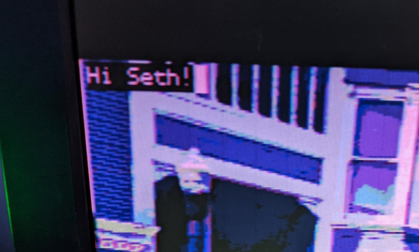
So we developed a method to handle this kind of pixel shifting to synchronize the pixel hardware with the VGA timing hardware.
Digital to Analog Converter (DAC)

Once the pixel byte has been taken out of the FIFO memory it’s on its way to being displayed by the monitor. To be displayed this pixel byte must be converted into three analog voltages between 0 and 0.7 volts corresponding to the Red, Green, and Blue color channels. We accomplished this with an R2R Resistor Ladder DAC.
In an R2R resistor ladder DAC the resistor network is commonly connected to an op-amp to maintain the output voltage regardless of what load the DAC is connected to. However in our case the load is only ever the 75 Ω impedance of the analog color lines in the monitor, which we can account for in the resistor ladder design. One concern, however, is that our resistor ladder can consume a fair amount of current because we’re going from 5 V input and dropping to under 1 V. The output pins representing the color coming from an IC may not be rated to supply the amount of current the DAC would need to maintain the voltage.
In an earlier version of the DAC this is what we did (copying Ben Eater’s video) but the colors will dull. We also tried an op-amp but that we saw some weird visual artifacts in the output. What seemed to work best was using a line driver to supply the resister ladder with enough current to prevent the voltage dropping too low. Now the colors are properly vivid.
IO Control
To actually function as a terminal Vgaterm must receive serial signals from a connected host on one of the four terminal IO ports (USB, pin headers, RS-232 over RJ45,RS-232 over DSUB-9 Serial) and update the video buffer accordingly. It also must handle keyboard input and forward those typed characters to the connected host.
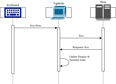
For keyboard input we went over several options including falling back on PS/2 protocol over USB and trying to write a basic software-driven USB host with the esp32c3 GPIO pins. But we settled on just using this USB host to UART converter by MatzElectronics.
Software, in a loop, waits for keyboard input or input by a connected host. When input is received on either, the CPU is interrupted. If receiving key presses, the character(s) are dequeued and passed along to the connected host. If receiving characters from the host, vgaterm updates the text buffer and cursor which updates the video memory. The updated video memory is then emitted in the next frame, showing the text to the user on screen.
Seth and I decided that this should never interrupt the CPU from emitting pixel bytes as we wanted to prevent any visual artifacts as much as possible. However this could mean it’s possible to drop characters if the CPU is overwhelmed with input. We landed on this decision because the chance of dropping characters seemed small and the display shaking and wobbling felt viscerally “broken”. We can also help mitigate the likelihood of dropping characters with some UART settings (Software Flow Control).
Closing Thoughts
This is only an overview of the operation and design of Vgaterm. My hope is that I can continue to make posts going into more detail about each of these major components. I learned so much working on this project and it gave me such joy to share it with a friend.
Working on this project challenged me technologically at every step but I always felt like I could make progress. And when I did despair and feel overwhelmed by a problem I couldn’t crack Seth would be there to help and together we’d make progress again. And likewise I would be there for Seth when he was stuck. For one of the first times I felt supported and heard in work. Our skills and outlooks complemented each other in a virtuous cycle. I could not have done this on my own, and together we made something and learned together which feels remarkable!
I have more hope, after this experience, that I can find and cultivate more working relationships that are nurturing, where we learn from each other, and that allow us to tackle problems that we couldn’t solve individually. Through community we can own and solve problems that collectively affect us.
This leads to how I began to change how I thought about open source and open hardware as Vgaterm was developed. Seth and I always wanted this to be open, but now I see us and our project as existing within and for the open source community and also in the greater maker and DIY community. Communities like knitters, gardeners, crafters, artists, DIY, home chefs and others all use a network of engaged and creative folks to pass around ideas to share - to collectively own the ideas of their particular craft for anyone to learn. I’ve started to see technology in a similar light.
I’ve realized that electronics and hardware and programming are just skills that someone can learn like any other, and that we, the community, can collectively own and build things that are important and useful - that we don’t have to capitulate to huge corporations that want to collect our data, exploit workers, or monopolize the objects and services in our daily lives. It feels like a way to fight against the enshittification that represents the current era in tech today. These are concepts I’m still thinking about and working through, and I have Vgaterm to thank for helping me engage with these ideas.